A hydraulic press closing a 500-ton deep-drawing die and an injection molding machine clamping a mold before a shot of molten plastic look nothing alike on the shop floor. Underneath, though, they run on the same logic: a hydraulic control valve — or more precisely, a coordinated set of them — has to switch the machine between fast, low-force movement and slow, high-force movement multiple times in a single cycle, hold that force steady for seconds at a time, and do it thousands of times a day without drift. Get the valve selection wrong, and the result isn’t subtle — wrinkled panels, flashed moldings, or a clamp that creeps open under pressure.
This article looks at how the three families of hydraulic control valves — directional, pressure, and flow — work together across a press or molding cycle, and which HFD Hydraulic valves are built for each stage.
Quick Overview: Hydraulic Control Valves in Presses and Injection Molding
What do hydraulic control valves do in a press or molding machine?
They switch the machine between fast approach and slow, high-force work, hold clamping or forming pressure steady during the dwell, protect the system from overload, and sequence the clamp, ram, and ejector so each moves only when it’s supposed to.
Key valve types and their roles:
- Directional control valves (e.g., HFD VE/B series) – route flow to the clamp cylinder, ram, or ejector, and switch each one open, closed, or in reverse
- High-low pressure valves (e.g., HFD VEP/FL) – combine a large and small pump so the press or clamp closes fast at low pressure, then switches automatically to high pressure for the final squeeze
- Pilot-operated relief valves with electric venting (e.g., HFD VMP/VE) – cap system pressure to protect tooling and seals, and unload the pump to near-zero pressure during dwell or cooling to cut energy use
- Cartridge flow regulators (e.g., HFD VDR, VDR/CO) – meter ram or platen speed so forming or mold-closing happens at a controlled, repeatable rate
- Sequence valves – enforce the order of operations, such as preventing the ejector from firing until the clamp is fully open
Example
An injection molding machine’s clamp cylinder closes fast at low pressure through a directional valve, then a high-low pressure valve switches the circuit to full clamping tonnage before injection starts. A relief valve caps pressure if the mold catches, and once packing is complete, the same relief valve vents the pump to idle during cooling to save energy.
Summary
Match valve type to the job the phase requires — directional for routing, high-low pressure and flow regulation for speed/force transitions, relief for protection and energy saving, sequence valves for order — and size each one to the press or machine’s peak flow and pressure, including the pressure spike at the moment of clamp lock-up.
Why These Machines Ask So Much of a Control Valve
Most hydraulic equipment repeats one motion — lift, lower, rotate. A press or injection molding machine asks a single hydraulic circuit to behave differently within seconds of itself. The platen or clamp needs to travel most of its stroke quickly, since dead time between cycles is wasted production. But the last few millimeters — where the die contacts the blank, or the mold halves seal against injection pressure — need to happen slowly and under tight force control, because that’s where wrinkling, flash, or tool damage actually occurs.
A hydraulic control valve is what makes that switch possible. In a press or molding machine, it’s rarely a single valve doing the work — it’s a directional valve, a pressure-control valve, and a flow-control valve, each handling one part of the transition, wired into the same circuit.

Directional Control: Routing Flow to Clamp, Ram, and Ejector
Every phase of a press or molding cycle starts with a directional control valve deciding where fluid goes. Closing the mold, holding it shut, opening it, and firing the ejector are four distinct flow paths through the same set of cylinders, and the directional valve is what switches between them.
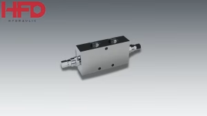
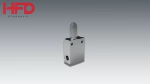
The HFD VE/B series 3-way pilot-operated directional control valve is built for exactly this kind of duty — high cycle counts, precise spool positioning, and the ability to be actuated by solenoid for automated, PLC-driven machines. Because it’s pilot-operated, it can shift a large main spool using only a small pilot signal, which matters on a press circuit where the main flow path may be sized for a large-bore clamp cylinder. For a closer look at how 2-way, 3-way, and 4-way directional valves differ and where each fits, see our directional control valve guide.
Peer-reviewed research on hydraulic injection molding machines describes this same architecture: solenoid valves sit between the pump and each section of the machine, and switching those valves reconfigures the hydraulic circuit to produce the different motions the molding cycle needs, giving flexible control over both flow rate and pressure. That’s a directional valve’s job description in one sentence — and it’s the same job a press’s clamp and ram circuits ask of a valve like the VE/B.
Fast Close, Then Full Force: Why These Circuits Need Two Pressure Ranges
Here’s the part of the cycle where presses and injection molding machines diverge most from ordinary hydraulic equipment. The clamp or ram doesn’t just need to move — it needs to move fast until the last moment, then generate very high force over a very short distance.
The common solution is a high-low pressure valve that pairs a large-volume pump with a small-volume, high-pressure pump. During the approach, both pumps feed the circuit for maximum speed at low pressure. Once the platen reaches working position, the valve unloads the large pump and lets the small pump build full pressure alone. Injection molding hydraulic system patents describe this exact arrangement — a solenoid valve switches in based on desired flow rate, so at high clamping speed the cylinder draws from both the large- and small-capacity pumps at once, then drops back to the small pump alone once full pressure is needed.
The HFD VEP/FL CETOP face-mounting high-low pressure valve performs this switch automatically based on system pressure, without needing a separate signal from the machine controller. On a press, this same two-stage logic is what lets a die close in a fraction of a second and still deliver full tonnage at the bottom of the stroke — the same principle used across deep-drawing and forming presses, which are valued specifically because, unlike mechanical presses, they deliver consistent full tonnage at any point in the stroke rather than losing force through mechanical leverage.
Protecting the System — and Saving Energy — with Relief Valves
Clamping tonnage and forming force both come from pressure, and pressure that isn’t capped will eventually find the weakest seal, hose, or casting in the system. A pressure relief valve is the safety layer that opens before that happens, diverting excess flow to tank if the circuit exceeds its set point — whether from a jammed die, a short shot, or simple thermal expansion during a long production run.
Presses and injection molding machines add a second requirement most other hydraulic equipment doesn’t have: long dwell times. Once a mold is clamped or a die is closed, the machine often needs to hold that position for several seconds — during injection, packing, and cooling — without doing any additional work. Running the main pump at full pressure through all of that time wastes energy for no mechanical benefit.
The HFD VMP/VE pilot-operated electric venting pressure relief valve addresses both needs in one component. It caps system pressure like a standard relief valve, but its electric venting function also lets the controller unload the pump to near-zero pressure during dwell or cooling — the pump keeps turning, but stops doing work — then re-pressurize instantly when the next phase begins. On machines running continuous multi-shift production, that idle-pressure reduction adds up across thousands of cycles.
Metering the Speed: Flow Control for Forming and Injection Precision
Directional and pressure valves decide where fluid goes and how hard it pushes; flow control valves decide how fast. In a forming press, ram speed through the working stroke directly affects part quality — too fast and the material tears or wrinkles, too slow and cycle time suffers for no quality benefit. In an injection molding machine, screw and platen speed affect fill pattern, weld lines, and dimensional consistency from shot to shot.
The HFD VDR cartridge pressure-compensated adjustable flow regulator and its fixed-setting counterpart, the VDR/CO, meter flow to hold a set speed regardless of load or pressure changes elsewhere in the circuit — the same pressure-compensation principle used in our flow control valve coverage, applied here to ram and platen motion instead of cylinder actuator speed. Because they’re cartridge-style, they mount directly into a manifold block close to the cylinder, which keeps response fast on circuits where the valve needs to react within a fraction of a second as the ram approaches the workpiece.
Sequencing: Making Sure Nothing Fires Out of Order
A press or molding cycle only works if its stages happen in a fixed order — the clamp has to fully close before injection starts, and the ejector can’t fire until the clamp has fully opened. Sequence valves enforce this by blocking flow to a secondary circuit until pressure in the primary circuit reaches a set threshold, so the machine can’t skip a step even if a solenoid signal arrives early or a sensor lags. We’ve covered how differential-piston sequence valves solve a related back-pressure problem without a separate drain line in our VDSD/B sequence valve article — the same pressure-threshold logic applies directly to clamp-to-injection and clamp-to-eject sequencing on these machines.

Selecting Control Valves for Press and Molding Duty
A few factors matter more here than on general-purpose hydraulic equipment:
Cycle rate and duty cycle. A press or molding machine running 15–30 cycles per hour puts far more switching cycles through a directional valve over a year than most mobile equipment sees in its service life. Spool and solenoid components need to be rated for that switching frequency, not just peak flow.
Response speed. Because the transition from fast approach to high-pressure work happens in a fraction of a second, valve response time affects part quality directly — a sluggish high-low pressure valve means the die or mold contacts the work at the wrong speed.
Contamination tolerance. Mold release agents, hydraulic fluid additives, and fine particulate from forming operations can find their way into the circuit over time. Valves with hardened spools and tight seal tolerances hold their calibration longer under these conditions.
Pressure margin. Because clamping and forming both involve a sharp pressure spike at lock-up, relief and sequence valves should be set with margin above the working pressure, not sized to the average pressure across the cycle.

Bringing It Together
A press or injection molding machine doesn’t run on one hydraulic control valve — it runs on a directional valve routing flow, a high-low pressure valve switching between fast approach and full force, a relief valve capping pressure and cutting idle energy use, and a flow regulator holding ram or platen speed steady through the working stroke. HFD Hydraulic’s VE/B, VEP/FL, VMP/VE, and VDR/VDR-CO valves are built to cover these roles individually, and to work together as a matched circuit.
Browse the full hydraulic control valve catalog or contact HFD Hydraulic to discuss valve selection for your press or molding line.