In the cylinder circuits of construction machinery, aerial work platforms, and mining equipment, pilot-operated check valves (commonly called hydraulic locks) and balance valves (counterbalance valves) are frequently confused. Although the two look similar in appearance, their internal structure, technical characteristics, flow and pressure output behavior, and applicable operating conditions differ enormously — an incorrect selection can easily lead to cylinder drift, shaking, shock, or even safety accidents. Drawing on years of experience in valve and lock R&D and system matching, HFD Hydraulic presents a systematic analysis across four dimensions — structural differences, technical characteristics, flow and pressure output characteristics, and application differences — to provide an accurate reference for system selection.
Quick Overview: Pilot-operated check valves and balance valves both hold cylinder position, but they’re not interchangeable. A pilot-operated check valve (like HFD’s VRDD, commonly called a hydraulic lock) is a simple on/off seal — ideal for horizontal or light-load cylinders with no risk of overrunning. A balance valve (like HFD’s VBCD SE) provides continuous, adjustable back-pressure — required for vertical lifting, tilting, or any load that can drive the cylinder to retract. Using a pilot-operated check valve alone on a heavy vertical lift is a safety hazard.


I. Structural Differences
Bidirectional Pilot-Operated Check Valve (Hydraulic Lock)
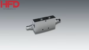
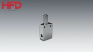
A bidirectional pilot-operated check valve — commonly called a hydraulic lock — is formed by two independent check-valve elements integrated in parallel. Its core consists of a conical sealing check-valve element plus a control-piston mechanism, with no pressure-regulating spring and no relief or throttling function — it is a purely on/off sealing valve (see Figure 1, structural diagram of the HFD Hydraulic VRDD-series pilot-operated check valve).
1. The valve core uses a high-precision conical hard-sealing structure, relying on a small return spring to fully close the oil path, giving high sealing accuracy.
2. It has no independent opening pressure — it relies solely on external control-oil pressure pushing the control piston to lift the check-valve core open and permit reverse flow.
3. It has no pressure-adjusting screw, no throttling passage, and no overload-relief structure — it has only two states: fully open and fully closed.
4. The structure is extremely simple; the core design goal is static, zero-leakage locking, with no dynamic adjustment capability.

Balance Valve (Counterbalance Valve)
A balance valve is essentially an externally piloted, check-type sequence valve. It integrates a check valve, a sequence throttle-valve core, a high-stiffness pressure-regulating spring, and a pressure-adjustment mechanism, with some models also incorporating an overload-relief function. It is a continuously adjustable pressure/flow control valve (see Figure 2, structural diagram of the HFD Hydraulic VBCD SE-series balance valve).
1. Forward oil path: oil pushes open the built-in check valve at low pressure, giving smooth flow with minimal resistance and low pressure loss.
2. Reverse oil path: relying on the pressure-regulating spring’s preset opening back-pressure, the valve core adjusts its opening steplessly, achieving throttled flow control rather than a simple on/off switch.
3. A built-in pressure-adjusting screw lets technicians fine-tune the balance pressure on site, matching the valve to whatever dead-weight load the system needs to counterbalance.
4. An integrated relief passage vents circuit shock pressure the instant it occurs, so the valve delivers speed control and overload protection at the same time.
Core structural difference: a hydraulic pilot-operated check valve is a purely on/off sealing element with no adjustment capability, while a balance valve is a continuously adjustable pressure/flow control element that combines sealing, throttling, pressure stabilization, and relief functions.

II. Differences in Technical Characteristics
| Comparison Item | Bidirectional Pilot-Operated Check Valve | Balance Valve (Counterbalance Valve) |
| Sealing performance | Conical hard sealing; extremely low internal leakage; excellent static pressure-holding, enabling long-term zero-drift locking. | Conical hard sealing; extremely low internal leakage; excellent static pressure-holding, enabling long-term zero-drift locking. |
| Operating mode | On/off operation: fully opens once control pressure is reached and fully closes once pressure is lost, with no intermediate adjustable opening. | Proportional operation: valve opening self-adjusts dynamically according to load pressure and pilot pressure (see Figure 3, Balance Valve Control Pressure vs. Opening/Flow Curve). |
| Back-pressure capability | No independent back-pressure; once open, return oil flows with no resistance, and external return back-pressure can easily disturb the control chamber, causing false opening or drift. | Actively establishes a stable counterbalancing back-pressure, suppressing overspeed descent under dead weight, with strong resistance to circuit back-pressure and pressure fluctuation. |
| Overload protection | No relief function; circuit pressure build-up or shock pressure cannot be released, easily damaging pipelines and cylinders. | Built-in relief/pressure-stabilizing function that releases shock pressure in real time, protecting hydraulic components and pipelines. |
| Motion stability | Under heavy dead-weight loads, the valve fully opens the instant it unlocks and the load free-falls, making shaking, nodding, oscillation, and shock likely. | Continuous dynamic pressure-stabilizing throttling throughout gives controllable, uniform, stable descent, eliminating cylinder drift and shaking. |
| Control logic | Threshold-type on/off control: fully opens once pressure is reached and locks immediately once pressure is lost, with no buffered transition. | Continuous closed-loop control: opening pressure, valve opening, and return flow dynamically match the load condition. |

III. Differences in Flow & Pressure Output Characteristics
Flow and pressure output characteristics are the core source of the two valves’ differing operating behavior, directly determining the smoothness of cylinder motion, speed controllability, and load safety. HFD Hydraulic distinguishes them precisely across five dimensions: flow rate, pressure, flow velocity, dynamic response, and oil-path state.
| Output Characteristic | Pilot-Operated Check Valve | Balance Valve |
| Forward oil-intake output (lifting/extension) | The check valve fully opens with maximum flow cross-section; flow has no throttling loss and very low pressure loss; extension speed follows pump-source flow, giving fast, lag-free response. | The built-in check valve fully opens at low pressure with pressure loss close to that of a pilot-operated check valve; flow output is stable during lifting, with no notable difference. |
| Reverse return-oil output (descent/retraction) | Once control pressure is reached the valve core opens instantly; return oil flows with no throttling and no speed limit, surging out in large instantaneous volume, driven entirely by the load’s dead weight — the pump source cannot constrain speed. | The return passage is dynamically throttled by the valve opening, giving self-adaptive, pressure-stabilized flow; the larger the load, the more the opening self-adjusts, keeping return flow constant and preventing sudden surges. |
| System pressure output state | Locked state: circuit pressure is fully sealed with no decay. Open state: return pressure drops to near zero with no back-pressure support, causing violent fluctuation. | Maintains a constant working back-pressure throughout, with continuous, stable output and no sudden rises or drops; automatically releases pressure under overload, keeping pressure always controllable. |
| Flow velocity and uniformity | Velocity is uncontrollable; it surges the instant the valve unlocks, prone to fast-then-slow motion and jerking, easily overspeeding or stalling under negative-load conditions. | Velocity is constant and controllable; throttling back-pressure offsets the dead-weight driving force, giving uniform output and smooth, low-speed motion with no overspeed or shaking. |
| Dynamic response and cavitation resistance | Abrupt on/off response with large negative-pressure fluctuations; heavy-load descent easily causes cavitation, noise, and pipeline shock. | Progressive opening response with smooth flow transitions and dynamic pressure/flow compensation, effectively suppressing cavitation and reducing noise and vibration. |
| Flow adaptability | Matches only a fixed pump-source flow rate and cannot adjust to load changes; flow does not match the load under negative-load conditions. | Self-adaptive: fine-tunes flow in real time according to load size and pilot pressure, matching variable-load and variable-flow conditions. |
Summary of core output differences: a pilot-operated check valve’s flow output follows a binary on/off mode — fully sealed or fully open, with no dynamic adjustment; a balance valve’s output follows a continuously adjustable, pressure-stabilized throttling mode, achieving dynamic closed-loop control of flow, pressure, and velocity suited to dynamic load conditions.
IV. Differences in Cylinder System Application
Applicable Conditions for Pilot-Operated Check Valves
Core role: static pressure-holding and locking — primarily for cylinder circuits with no risk of dead-weight descent that must hold position over the long term.
1. Horizontal cylinders: clamping cylinders, translating worktables, horizontal push-pull mechanisms — positions that must stay drift-free for long periods after shutdown.
2. Small-dead-weight vertical cylinders: small fixtures/tooling and light-load lifting mechanisms, where the dead weight is minimal, there is no overspeed-descent risk, and the priority is holding position perfectly still when stopped.
3. Circuit characteristics: cylinder motion requires no speed limiting, there is no negative-load driving force, and the only safety risk is positional drift when stopped.
⚠ Selection taboo: strictly prohibited for standalone use on large-dead-weight vertical lifting cylinders. If a heavy vertical cylinder is fitted with only a pilot-operated check valve, oil flows uncontrolled the instant it unlocks, the load descends rapidly, and pressure fluctuations cause the valve to open and close repeatedly — producing severe shaking and shock, a major safety hazard.
Applicable Conditions for Balance Valves
Core role: dynamic counterbalancing and speed-limiting/anti-drop protection — primarily for vertical or inclined cylinders subject to overturning dead weight or negative-load driving forces.
1. Lifting-type cylinders: crane luffing-jib cylinders, aerial work platform lift cylinders, dump-truck tipping cylinders, and construction-machinery outrigger cylinders.
2. Negative-load conditions: any equipment where the load’s dead weight can actively push the cylinder to retract, making it prone to overspeed drift or stall-descent.
3. Circuit characteristics: cylinder motion must be controllable, speed-limited, smooth, and shock-free, with dynamic operating safety as the priority.
V. Recommendations for Combined Selection in Engineering
1. Horizontal cylinders, tooling/fixtures, and light-load positioning/pressure-holding conditions: select a pilot-operated check valve directly. It meets the need for long-term, zero-drift locking and static pressure-holding, with high cost-effectiveness and strong stability.
2. Vertical lifting, tilting, load-hoisting, and heavy-duty outrigger conditions: prioritize a balance valve. Its dynamic throttling and pressure stabilization limit descent speed, prevent cylinder drift, and resist shock, ensuring operating safety.