In the world of hydraulic systems, few components are as important as the directional solenoid valve when it comes to controlling where your fluid flows and how your machinery moves. These electromechanical devices control the path of hydraulic fluid, determining where power goes and how machinery moves. Here’s the thing: whether you’re designing a brand-new system or breathing new life into existing equipment, understanding these valves can mean the difference between smooth operations and frustrating breakdowns.
Quick Overview: Directional Solenoid Valves
What is a directional solenoid valve and how does it work?
A directional solenoid valve is an electromechanical valve that uses an electromagnetic coil to shift an internal spool or poppet, redirecting hydraulic fluid to different ports on command. Energizing the coil generates a magnetic field that repositions the valve internals — opening the correct flow path while blocking others — enabling precise, remote control of cylinders, motors, and actuators without manual valve operation.
Key configurations and when to use each:
- 2/2 valve – 2 ports, 2 positions; simple on/off flow control for basic isolation applications
- 3/2 valve – pressure, work, and exhaust ports; correct choice for single-acting cylinder control
- 4/3 valve – 4 ports, 3 positions (extend, neutral, retract); most flexible configuration for double-acting cylinder control
- HFD VE/B/VMP/VUI/SR series – purpose-built for single-acting cylinder applications; flow ratings from 20 to 160 L/min; max pressure 350 bar
- Voltage options – 12V DC, 24V DC, 110V AC, 220V AC; must match control system to prevent coil burnout
Example
A dump truck’s hydraulic tipping system uses a directional solenoid valve to raise and lower the bed from the cab via a switch. Energizing solenoid A directs pump flow to the lift cylinder to raise the bed; energizing solenoid B connects the cylinder to tank, allowing controlled lowering — all without the operator leaving the cab or touching a manual valve.
Summary
Select a directional solenoid valve by matching port configuration to cylinder type (single or double-acting), sizing flow capacity with a 20–30% margin above system demand, and verifying pressure rating against peak system pressure including transient spikes — then confirm voltage, mounting, and port thread compatibility before ordering.
What Is a Directional Solenoid Valve?
A directional solenoid valve is an electrically operated valve that controls the direction of fluid flow in hydraulic circuits. Unlike manual valves that require physical manipulation, solenoid valves use electromagnetic coils to shift internal spools or poppets, redirecting hydraulic fluid to different ports. This automation enables precise, remote control of hydraulic actuators, cylinders, and motors.
The term “directional” refers to the valve’s primary function: directing pressurized fluid along specific pathways. Here’s how it works: flip the switch, and the solenoid coil generates a magnetic field that repositions the valve internals, opening the right passages while blocking off others. This mechanism allows operators to control complex machinery from a safe distance or through automated control systems.
How Directional Control Valves Work
At their core, hydraulic directional valves operate on a simple principle: controlled fluid redirection. The main components include the solenoid coil (which converts electrical energy into mechanical motion), the valve body (housing internal passages and ports), the spool or poppet (the moving element), a return spring, and port connections typically labeled P (pressure/pump), T (tank/return), and A and B (work ports).
When voltage is applied to the solenoid coil, it generates a magnetic field that pulls the armature and attached spool against spring pressure. This movement realigns internal passages, connecting different ports. For example, energizing one solenoid might connect P to A and B to T, extending a cylinder. Energizing the opposite solenoid reverses these connections, retracting the cylinder.
Understanding Valve Configurations
Directional control valves are classified by their number of ports and positions. A 2/2 valve has 2 ports and 2 positions, offering simple on/off control. A 3/2 valve includes a pressure port, work port, and exhaust port, making it ideal for single-acting cylinders. The 4/3 configuration (4 ports, 3 positions) gives you the most flexibility—you can set that center position to closed, open, or somewhere in between depending on what your application needs.
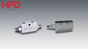
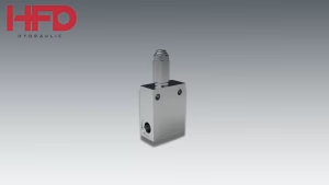
The HFD Hydraulic VE/B/VMP/VUI/SR series represents a specialized directional solenoid valve designed specifically for single-acting cylinder applications. This focused design cuts out the unnecessary complexity while still delivering robust performance—with rated flows from 20 L/min all the way up to 160 L/min and pressure ratings that max out at 350 bar.

Reading Hydraulic Symbols and Diagrams
Understanding hydraulic schematics is essential for anyone working with directional valves. Port designations follow standard conventions: P for pressure inlet from the pump, T for tank return line, A and B for work ports connected to actuators, and X or Y for pilot ports if applicable.
In hydraulic symbols, squares represent valve positions, arrows show flow direction, lines indicate connections between ports, springs show return mechanisms, and coil representations indicate the actuation method. The flow-pressure drop curves accompanying these diagrams tell you how much pressure you’ll lose at different flow rates, critical information for system sizing and efficiency calculations.
Single-Acting vs. Double-Acting Cylinder Control
The choice between valve types often depends on your cylinder configuration. Single-acting cylinders extend using hydraulic pressure but retract using spring force or gravity. They require simpler valve configurations since hydraulic power only needs to flow in one direction. The VE/B/VMP/VUI/SR series excels in these applications, offering advantages including simpler hydraulic circuits, lower energy consumption, reduced heat generation, more compact valve design, and lower initial cost.
Double-acting cylinders require hydraulic power for both extension and retraction, necessitating more complex valve configurations with bidirectional flow control. While more versatile, they require larger, more expensive valves and consume more energy.
Technical Specifications That Matter
When selecting a directional solenoid valve, several specifications determine suitability for your application:
Flow Capacity is measured in liters per minute (L/min) and must exceed your system’s maximum demand. Undersized valves create excessive pressure drop, generating heat and reducing efficiency. The VE/B/VMP/VUI/SR series comes in multiple flow ratings—20, 50, 65, 90, and 160 L/min—so you can match it to your specific cylinder size and speed needs.
Pressure Rating determines the valve’s durability under system loads. Always select valves rated above your system’s maximum pressure, including pressure spikes. Operating at or near maximum ratings reduces service life.
Voltage Requirements vary (12V DC, 24V DC, 110V AC, 220V AC). Match the valve voltage to your control system to avoid compatibility issues and potential coil burnout.
Response Time affects cycle times and system responsiveness. Industrial applications typically require response times between 20-100 milliseconds.
Understanding Flow-Pressure Drop Curves
The flow-pressure drop curves shown in technical documentation reveal crucial performance characteristics. These graphs plot pressure loss against flow rate for each valve size. As flow increases, pressure loss through the valve rises exponentially, following fluid dynamics principles where pressure drop increases with the square of velocity.
By finding your required flow rate on the horizontal axis, you can determine the expected pressure drop. Aim for operation in the lower portion of the curve where pressure drop remains reasonable. Lower pressure drop means less energy wasted as heat and better system efficiency. A valve showing 10 bar drop at 50 L/min generates approximately 830 watts of heat that must be dissipated.
Real-World Applications
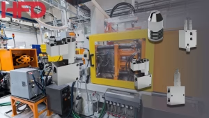
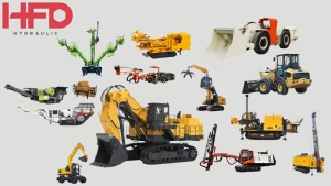
Directional solenoid valves serve countless industries. In construction equipment, excavators and loaders use multiple directional valves to control boom, arm, bucket, and track movements. Manufacturing machinery like presses and injection molding machines rely on precise directional control for positioning and clamping operations.
Agricultural equipment uses hydraulic valves to control implements and adjust cutting heights. Material handling equipment including forklifts and cranes depends on directional control valves for safe load manipulation. Mobile hydraulics in dump trucks and delivery vehicles incorporate directional valves for body control and specialized equipment activation. Industrial automation systems use electrically controlled hydraulic valves for coordinated motion control integrated with PLCs.

Selecting the Right Valve for Your Application
Choosing the appropriate directional control valve requires systematic analysis. Start by defining your requirements: cylinder type, required flow rate, system pressure range, available electrical power, environmental conditions, and mounting preferences.
Calculate performance needs by determining required flow using the formula: Q = (A × L) / T, where Q is flow rate (L/min), A is cylinder area (cm²), L is stroke length (cm), and T is desired cycle time (seconds). Add 20-30% margin for pressure drop through hoses, fittings, and the valve itself.
Match your requirements against available specifications. For the HFD VE/B/VMP/VUI/SR series, options include VE/B/VMP/VUI/SR 16(WL) at 20 L/min, VE/B/VMP/VUI/SR 32(WL) at 50 L/min, VE/B/VMP/VUI/SR 16(CWAL) at 65 L/min, VE/B/VMP/VUI/SR 32(WAL) at 90 L/min, and VE/B/VMP/VUI/SR 10(2WAL) at 160 L/min.
Consider how the valve integrates with your system, including mounting configuration compatibility, electrical connection type, port size and thread type, available space constraints, and maintenance accessibility. Assess the environmental factors to make sure the valve can hold out your operating temperature range, contamination levels, vibration and shock loads, and potential corrosive atmosphere exposure.
Installation Best Practices
Proper installation ensures reliable operation and long service life. Before you start, make sure to thoroughly clean all hydraulic lines, double-check that your electrical supply matches what the valve needs, verify your port sizes and threads are compatible, and ensure you’re working with a flat, clean mounting surface.
When mounting, torque mounting bolts to manufacturer specifications, use proper thread sealant or O-rings as specified, orient the valve correctly for gravity drainage, and provide adequate clearance for solenoid replacement. For hydraulic connections, use appropriate hose or tubing sizes to minimize restriction, install pressure gauges for system monitoring, add filtration to protect internal components, and route lines to avoid kinking and chafing.
Electrical connections require properly rated wire gauge for solenoid current, overcurrent protection, sealed connectors in harsh environments, and consideration for surge suppression on long cable runs. During system commissioning, gradually bring the system to pressure while checking for leaks, verify solenoid actuation in both directions, monitor operating temperature during initial cycles, and document baseline performance for future reference.
Maintenance and Troubleshooting
Regular maintenance prevents unexpected failures and extends component life. Daily or weekly checks should monitor for external leaks, check operating temperature, listen for unusual sounds, and verify consistent operation. Monthly maintenance includes inspecting electrical connections, checking mounting bolt torque, monitoring system pressure trends, and testing safety features.
Quarterly tasks involve analyzing hydraulic fluid condition, checking filter contamination, measuring response times, and documenting performance changes. Annual maintenance should include replacing hydraulic fluid and filters, inspecting internal components if accessible, testing electrical insulation, and calibrating instrumentation.
Common issues include valves that won’t shift (check electrical supply, verify solenoid coil continuity, inspect for mechanical binding), slow operation (review flow-pressure drop curves, check for contamination, verify adequate pump capacity), external leakage (inspect O-rings and seals, check for loose connections), and overheating (reduce cycle frequency, check for excessive pressure drop, verify proper fluid viscosity).
Advanced Considerations
Standard directional solenoid valves operate in discrete positions, but proportional valves offer variable positioning for precise flow control and smooth acceleration. While more expensive, proportional valves reduce shock loads and enable sophisticated motion profiles.
Multiple valves can be integrated into manifold blocks, reducing piping, leak points, and installation space. Manifolds also facilitate easier maintenance and system modifications. Modern industrial controls demand seamless integration through fieldbus compatibility, built-in diagnostics, position feedback sensors, and programmable response characteristics.
Optimize energy efficiency by properly sizing valves to minimize pressure drop, using load-sensing systems, implementing accumulator circuits, and considering electro-hydraulic alternatives for low-duty cycles.
Why the VE/B/VMP/VUI/SR Series Stands Out
HFD Hydraulic’s directional solenoid valve line addresses specific needs in single-acting cylinder applications. By focusing on single-acting cylinder control, the VE/B/VMP/VUI/SR series eliminates unnecessary complexity while maintaining robust performance. The broad range covers flows from 20 to 160 L/min, accommodating everything from small auxiliary functions to primary hydraulic circuits.
The compact manifold design provides excellent structural integrity while minimizing installation space. Complete flow-pressure drop curves enable precise system design, eliminating guesswork and ensuring optimal performance across the operating range. Multiple model variants within each size offer flexibility in port configurations and mounting options to suit diverse applications.

The directional solenoid valve remains fundamental to modern hydraulic systems, providing reliable, precise control of fluid power. Understanding valve operation, proper selection criteria, and maintenance requirements ensures optimal system performance and longevity.
Whether you’re designing new equipment or maintaining what you already have, taking the time to choose the right valve pays off big—you’ll see better reliability, lower energy bills, and reduced ownership costs over the long haul. The HFD VE/B/VMP/VUI/SR series exemplifies how focused engineering creates solutions optimized for specific applications.
Ready to specify the right directional solenoid valve for your application? Visit HFD Hydraulic’s product page to explore the complete VE/B/VMP/VUI/SR series specifications and find the perfect match for your hydraulic system needs.