When you’re working with hydraulic systems, you need to make sure the fluid flows in the right direction. If it doesn’t, your system won’t work well and could even be unsafe. Out of all the hydraulic parts out there, inline hydraulic check valves are really key. They’re small enough to fit almost anywhere but still give you solid control over your fluid flow. You’ll find these valves in most modern hydraulic setups now, especially when space is limited or you need flexibility in how you install things.
Unlike traditional check valves that require separate mounting blocks or manifolds, inline hydraulic check valves offer a streamlined solution that integrates directly into hydraulic lines. This setup makes installation easier and actually works better too, which is why you see them a lot in mobile equipment, when you’re upgrading old systems, or anywhere space is really tight.
Quick Overview: Inline Hydraulic Check Valves
What is an inline hydraulic check valve and what does it do?
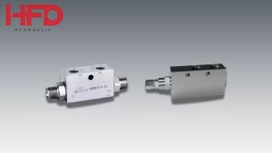
An inline hydraulic check valve is a compact, self-actuating valve that installs directly into a hydraulic line — allowing fluid to flow freely in one direction while automatically blocking reverse flow. Unlike traditional check valves that require separate mounting blocks or manifolds, inline designs thread directly into existing hydraulic lines using standard fittings, making them the preferred choice for space-constrained mobile equipment, system retrofits, and applications requiring precise flow direction control exactly where it is needed.
Main types and their key characteristics:
- Ball check valve (VUI) – spherical ball seals against conical seat; simple, reliable, self-cleaning; suited to general-purpose backflow prevention at low-to-medium pressure
- Poppet check valve (VUR) – guided poppet provides large flow area with minimal pressure drop; excellent sealing under high reverse pressure; preferred for high-pressure hydraulic circuits
- Poppet type flow restrictor with check valve (VSRU/C) – combines adjustable or fixed flow restriction in one direction with free check valve return flow; eliminates the need for a separate check valve alongside the flow control
- Spring-loaded designs – adjustable cracking pressure; rapid response and positive closure even at low reverse pressure; used where backflow prevention is critical regardless of reverse pressure level
Example
An excavator boom circuit uses a poppet-type inline check valve at the cylinder inlet to prevent boom drift when the operator releases the controls. The valve opens in milliseconds when the directional control valve commands movement, then seals instantly when flow stops — maintaining exact boom position under load with near-zero leakage between work cycles.
Summary
Choose an inline hydraulic check valve when backflow prevention, load holding, or circuit isolation is needed at a specific point in an existing hydraulic line — select ball type for simplicity, poppet type for high-pressure sealing, and poppet-with-restrictor when flow control and backflow prevention are both required in a single compact component.
What is the Purpose of an Inline Check Valve?
The fundamental purpose of an inline hydraulic check valve centers on providing directional flow control while minimizing space requirements and installation complexity. Think of these valves like gatekeepers – they let fluid through in one direction but block it from going the wrong way, which could cause problems or safety issues.
Installing them this way handles most of the typical problems you see in hydraulic systems. First off, you don’t need complicated manifold systems or mounting brackets – you can just put them right into the hydraulic lines you already have. This way you have fewer spots that could leak and the layout is much simpler. That’s especially important in mobile equipment because every connection point is another thing that might fail.
Since inline hydraulic check valves don’t take up much space, they’re perfect when you’re upgrading older systems and have to work with whatever room you’ve got. Rather than requiring significant system redesign to accommodate traditional check valves, inline variants can be installed directly into hydraulic lines with minimal modification to surrounding components.
Plus, you can put these valves right where you need them, so there’s less distance between the valve and whatever component you’re trying to protect. When they’re right there, the response time is much faster and you get more precise control. That’s especially important when the flow conditions are changing fast and you need the system to keep up.
What is the Purpose of a Hydraulic Check Valve?
Check valves have a few key jobs in hydraulic systems, but the big one is preventing reverse flow that might wreck your equipment or create dangerous situations. These valves work automatically based on pressure – they open when there’s enough forward pressure to push through, and snap shut when fluid tries to flow backward.
The protective function of hydraulic check valves extends beyond simple flow direction control. They help maintain pressure in specific sections of the circuit, so you don’t get pressure drops that mess with how the system works. Keeping that pressure is especially critical when hydraulic cylinders have to support weight or fight against outside forces trying to push back.
Check valves also help make the system more energy efficient. They prevent fluid from flowing backward, which cuts out the energy waste from fluid circulating in the wrong direction. This really matters in systems with lots of actuators or complicated setups where fluid taking the wrong path could really hurt how the whole system works.
From a safety standpoint, these valves are crucial because reverse flow can be downright dangerous in certain systems. In vertical applications, check valves prevent uncontrolled descent of loads, while in pressure-sensitive applications, they protect components from damaging pressure surges or vacuum conditions.
How Does an Inline Check Valve Work?
The operating mechanism of an inline hydraulic check valve relies on pressure-responsive flow control that automatically adapts to changing hydraulic conditions. The valve’s internal structure typically consists of a spring-loaded poppet, ball, or disc that seals against a precisely machined seat when no forward flow pressure is present.
When the forward pressure gets high enough to beat the valve’s cracking pressure, it pushes the internal part past the spring force and moves it away from the seat. This creates an opening so fluid can flow through without losing much pressure. The valve opening size varies proportionally with the pressure differential, providing smooth flow characteristics across the operating range.
How the spring is set up makes a huge difference in valve performance. Light springs open easily with low pressure, which is good when you don’t want much pressure drop. Heavy springs need more pressure to open but do a better job stopping reverse flow when that’s really important. The spring also ensures rapid valve closure when forward pressure decreases, preventing any reverse flow from establishing.

With inline setups, you need to pay attention to how the flow moves through the valve – you want to keep pressure loss low while still sealing properly. The newer inline check valves have smoother internal passages that cut down on turbulence and pressure loss, so you get better fluid flow while still preventing backflow.
When reverse pressure hits, it pushes the internal component harder against the seat, creating a tight seal that prevents any flow from going backward. The higher the reverse pressure gets, the better the seal becomes, which makes these inline valves really good for high-pressure systems where you absolutely can’t have reverse flow.
What is the Function of Inline Check Valve?
Inline hydraulic check valves do a lot more than just control which way fluid flows – they handle several important jobs in hydraulic systems. The main job is keeping the hydraulic system working properly by stopping reverse flow that could hurt performance or cause safety problems.
One key thing these valves do is help hold loads in place when hydraulic cylinders have to resist external forces trying to move them. Because the valve can seal against backward pressure, loads stay put even when the system pressure fluctuates or gets shut down. This is really important in vertical setups where gravity could otherwise make things drop or move when you don’t want them to.
Another key thing they do is isolate circuits, so different sections of the hydraulic system can operate independently without interfering with one another. Inline check valves enable complex systems to maintain pressure in specific branches while allowing other areas to cycle or operate at different pressures. You really need this isolation capability when you’ve got multiple actuators or parts of the system that work differently.
The function of preventing pump cavitation becomes important in systems where reverse flow could create vacuum conditions at the pump inlet. By keeping pressure up in the supply lines, inline hydraulic check valves prevent pump damage and make sure performance stays consistent even when loads fluctuate.
System efficiency improvement represents an often-overlooked function of inline hydraulic check valves. Since they prevent backflow, you don’t waste energy on fluid circulating in the wrong direction. This efficiency boost really matters in big systems or when you need to save as much energy as possible.
What is a Hydraulic Check Valve Used For?
You’ll find hydraulic check valves in tons of different industries and system configurations, where they handle critical functions in mobile equipment and stationary systems alike. Their versatility makes them necessary for all kinds of applications – from simple load holding jobs to complex multi-circuit systems where you need precise flow control.
Construction equipment is one of the biggest places where you’ll find hydraulic check valves. On excavators, they prevent the boom cylinders from drifting down when you release the controls, which lets you maintain exact positioning for precision work. Similarly, in hydraulic hammers, check valves ensure consistent operation by preventing reverse flow that could disrupt the hammering cycle.
Manufacturing systems use hydraulic check valves heavily to maintain pressure in things like hydraulic presses, injection molding machines, and automated assembly gear. You need exact pressure control and positioning accuracy in these applications, and that relies on dependable flow direction control. These valves keep hydraulic cylinders from moving during forming operations and prevent backflow that might hurt product quality.
Agricultural machinery uses hydraulic check valves to implement control systems, three-point hitch mechanisms, and steering systems. Farm equipment operates in harsh conditions where reliability is crucial, so these valves need to function consistently despite dirt, moisture, and temperature extremes.
Material handling equipment, including forklifts, cranes, and conveyor systems, depends on hydraulic check valves for safe load handling. These valves prevent loads from falling out of control and keep lifting mechanisms from moving even if power goes out or pressure changes.
Aerospace applications need hydraulic check valves that meet really strict reliability and performance standards. They control things like flight control surfaces, landing gear systems, and other crucial components where if something goes wrong, it could be disastrous. The space and weight limits in aerospace make inline hydraulic check valves really useful.
Types of Inline Hydraulic Check Valves
Ball Check Valves
Ball check valves represent the most common type of inline hydraulic check valve, utilizing a spherical ball that seats against a conical or flat seat to prevent reverse flow. The ball follows the internal geometry of the valve, which gives you good sealing while minimizing pressure loss when fluid flows forward.

The benefits of ball check valves are that they’re simple to design, operate reliably, and are relatively inexpensive. The spherical ball gives good sealing and does some self-cleaning, so it maintains performance even when there’s contamination around. However, ball check valves may exhibit higher pressure drops compared to other designs and can be sensitive to contamination that affects ball movement.
Poppet Check Valves
Poppet check valves employ a guided poppet or plunger that moves axially within the valve body to control flow. The poppet seals against a precisely machined seat when closed and retracts into the valve body when open, creating a large flow area with minimal pressure drop.

These valves give you excellent flow and can take high flow rates while keeping pressure drop relatively low. The way the poppet is guided provides solid sealing and reliable performance, so they’re good for high-pressure applications. However, poppet check valves typically require more complex manufacturing processes and may be more expensive than ball-type valves.
Swing Check Valves
Swing check valves utilize a hinged disc or flapper that swings open during forward flow and closes against a seat to prevent reverse flow. The inline configuration of swing check valves requires careful design to ensure proper operation in any mounting orientation.
The primary advantage of swing check valves is their low pressure drop during forward flow, as the disc swings completely out of the flow path. However, they may be more sensitive to mounting orientation and can exhibit slower response times compared to spring-loaded designs.
Spring-Loaded Check Valves
Spring-loaded check valves incorporate a spring mechanism that provides positive closure force, ensuring reliable sealing even at low reverse pressures. The spring force can be adjusted to set the valve’s cracking pressure, providing customizable performance characteristics.
These valves offer rapid response times and reliable sealing across a wide range of pressures. The spring mechanism ensures positive closure even in applications with minimal reverse pressure, making them ideal for applications where backflow prevention is critical.
Design Considerations for Inline Hydraulic Check Valves
Pressure Rating and Flow Capacity
Selecting appropriate pressure ratings requires careful analysis of maximum system pressure plus safety margins for pressure spikes and transient conditions. The valve must withstand not only normal operating pressure but also potential pressure surges that could occur during system startup, shutdown, or emergency conditions.
Flow capacity considerations involve both forward flow requirements and the acceptable pressure drop across the valve. Inline hydraulic check valves must provide sufficient flow area to handle peak flow demands while maintaining pressure drops within acceptable limits. The relationship between flow rate and pressure drop isn’t linear, which means you have to look closely at your operating conditions.
Material Selection and Compatibility
How well the materials work with hydraulic fluids directly affects how long the valve lasts and how well it performs. Standard steel and cast iron components handle petroleum-based fluids well, while synthetic fluids may require specialized materials or coatings to avoid degradation.
You need to consider temperature when picking materials and making sure seals are compatible. High-temperature applications might need heat-resistant materials and special seals, while low-temperature operations need materials that stay flexible and seal effectively.
Installation and Mounting Considerations
The inline configuration requires attention to flow direction marking and proper orientation during installation. Many inline hydraulic check valves incorporate flow direction arrows or other indicators to ensure correct installation.
Pipe sizing and connection types must be carefully selected to minimize pressure drops and ensure reliable sealing. Getting the threads right, setting up seals properly, and using correct torque specs all impact installation success and how the valve performs long-term.
Maintenance and Serviceability
Inline hydraulic check valves require consideration of maintenance access during system design. The inline design makes installation straightforward, but maintenance can be more complicated when you need to take the valve out or fix it.
Some inline designs incorporate removable cartridges or serviceable components that allow maintenance without complete valve replacement. You can save quite a bit on maintenance costs and avoid as much downtime this way.
Applications in Mobile Equipment
Construction Machinery
Some of the most challenging applications for inline hydraulic check valves are in construction equipment. Between the harsh environment, high pressures, and dynamic loads, these valves have to perform reliably despite dirt, moisture, and temperature extremes.
In excavators, these inline hydraulic check valves go in the boom, bucket, and swing circuits to stop drift and maintain exact positioning. The valves must respond quickly to operator inputs while reliably holding loads during delicate operations. The space limitations in mobile equipment make the compact inline design especially useful.
Agricultural Equipment
Agricultural machinery operates in environments where contamination and temperature variations are common challenges. Inline hydraulic check valves in tractor implement systems must function reliably despite exposure to dirt, crop residue, and varying weather conditions.
Three-point hitch systems rely on inline hydraulic check valves to maintain implement position during field operations. The valves prevent implements from drifting during transport and ensure consistent depth control during cultivation operations.
Material Handling Equipment
Forklifts and other material handling equipment depend on inline hydraulic check valves for safe load handling. The valves prevent uncontrolled descent of loads and ensure that lifting mechanisms maintain position even during power loss or system pressure fluctuations.

The small size of inline hydraulic check valves makes them ideal for forklift applications where space is limited and you need to be careful about weight distribution. The valves must provide reliable operation while minimizing the overall system footprint.
Installation Best Practices
Proper Orientation and Flow Direction
Correct installation orientation is crucial for optimal performance of inline hydraulic check valves. Most valves incorporate flow direction arrows or other indicators to ensure proper installation, but understanding the consequences of incorrect orientation is important for troubleshooting and maintenance.
Vertical installations require special consideration of gravity effects on valve operation. While most inline hydraulic check valves can operate in any orientation, some designs may exhibit different performance characteristics depending on mounting position.
System Flushing and Contamination Control
Pre-installation system flushing is essential to remove contamination that could affect valve performance. Even small particles can interfere with sealing surfaces or restrict valve movement, leading to reduced performance or premature failure.
Proper filtration system design ensures that contamination levels remain within acceptable limits throughout system operation. The inline configuration makes contamination control particularly important, as valve service may require system shutdown and line disconnection.
Torque Specifications and Seal Integrity
Proper torque application during installation ensures reliable sealing without damaging threads or valve components. Over-tightening can distort valve bodies or damage sealing surfaces, while under-tightening may result in external leakage.
Choosing the right thread sealant and applying it properly affects whether the seal will last. Proper sealant application prevents external leakage while avoiding contamination of the hydraulic fluid.
Troubleshooting Common Issues
Reverse Flow Problems
Reverse flow through inline hydraulic check valves typically indicates internal wear, contamination, or improper installation. You need to systematically test pressure and analyze valve operation under different conditions to diagnose problems.
If there’s contamination on the sealing surfaces, the valve won’t close right, which allows reverse flow even though the valve looks like it’s functioning normally. Most contamination problems can be avoided with regular system filtration and maintenance.
Excessive Pressure Drop
High pressure drop across inline hydraulic check valves may indicate restrictions in the valve’s internal flow path, improper sizing, or contamination buildup. Comparing actual pressure drop to manufacturer specifications helps identify abnormal conditions.
Getting the valve size wrong can cause too much pressure drop, which affects how well the system performs and how efficient it is. To size things properly, you need to analyze flow requirements and pressure drop limitations.
Valve Chatter and Noise
Valve chatter typically results from unstable flow conditions, improper valve sizing, or system resonance effects. The inline configuration can be particularly susceptible to flow-induced vibrations that cause valve instability.
You can use system damping methods like accumulators or restrictive orifices to reduce valve chatter and improve overall system stability. Proper valve sizing and system design also minimize the likelihood of chatter problems.
Future Trends and Innovations
Smart Valve Technology
Integrating electronic monitoring and control into inline hydraulic check valves represents a big advancement in valve tech. Smart valves offer real-time performance data, diagnostic details, and predictive maintenance features.
With wireless communication, you can remotely monitor how the valve is performing and check system conditions. This is especially useful in mobile equipment where regular inspection might be difficult or not practical.
Advanced Materials and Coatings
New materials and surface treatments are extending the operating life and performance capabilities of inline hydraulic check valves. These advanced coatings hold up better to wear and are compatible with more hydraulic fluids.
Composite materials can be used to make things lighter without losing strength or durability for inline hydraulic check valves. These materials are really helpful in mobile applications since lighter weight means better fuel economy or higher payload capacity.
Miniaturization and Integration
Ongoing miniaturization efforts are producing increasingly compact inline hydraulic check valves that provide enhanced performance in smaller packages. This is particularly important for mobile equipment since space constraints keep getting worse. Combined check and relief valve functions, for example, can provide both flow direction control and pressure protection in a single inline package.
Inline hydraulic check valves are really important parts of today’s hydraulic systems. They handle the flow control you need while working around space limitations and installation problems. Because they’re small, dependable, and work in so many applications, you can’t do without them. They’re used in everything from construction equipment to precision industrial machines.
Inline hydraulic check valve technology keeps evolving because people want better performance, reliability, and integration. This ensures they’ll stay important as hydraulic system design continues to develop. With systems getting more complicated and space constraints becoming harder to deal with, the role of inline hydraulic check valves in enabling efficient, reliable operation will only keep growing.
Engineers and technicians working with modern hydraulic systems need to understand how to properly select, install, and maintain inline hydraulic check valves. When hydraulic system designers take advantage of inline design while dealing with the challenges these valves bring, they can build systems that are more efficient, reliable, and easier to maintain. These systems can indeed handle today’s demanding requirements.