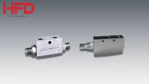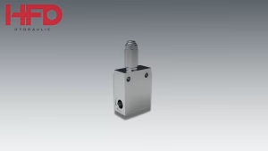
Any hydraulic system that lifts, lowers, or swings a load has one moment where things can go wrong quietly: the instant the operator lets go of the control and gravity, momentum, or an unbalanced load tries to keep moving on its own. An overcenter valve is the component built to catch exactly that moment — it holds the actuator in place until a real, pressure-confirmed command tells it to move, and it does this whether the system is sitting idle or actively fighting an overrunning load mid-motion.
The term shows up constantly in mobile hydraulics catalogs, crane and winch documentation, and valve manufacturer spec sheets, often right next to (or interchanged with) “counterbalance valve.” This guide covers what an overcenter valve actually is, how its internal mechanism works, the difference between single and double configurations, and what to look at when specifying one.
Quick Overview
- An overcenter valve is a load-holding and motion-control valve mounted at or near a hydraulic actuator to stop uncontrolled movement from an overrunning load.
- It works using two internal sections: a check section that allows free flow into the actuator, and a pilot-operated relief section that blocks reverse flow until a genuine pilot signal confirms commanded movement.
- Single overcenter valves hold a load in one direction (cranes, winches, aerial lifts); double overcenter valves hold loads in both directions (cylinders that go “over center,” bidirectional booms, closed-center circuits).
- Pilot ratios typically range from 3:1 to 8:1 depending on how dynamic the load is — higher ratios suit fast-changing, direction-reversing loads.
- “Overcenter valve,” “motion control valve,” and “counterbalance valve” are often used interchangeably, though the two terms carry slightly different technical connotations.
What Is an Overcenter Valve?
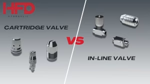
An overcenter valve is a load-holding cartridge or in-line valve installed at or very close to a hydraulic actuator’s port. Structurally, it combines two functions in one body:
- A check section, which allows unrestricted flow into the actuator during normal operation.
- A pilot-operated relief section, which blocks flow out of the actuator until a pilot signal — drawn from pressure on the opposite side of the actuator — confirms the directional valve is genuinely commanding motion.
The name “overcenter” comes from the valve’s role in handling loads that can pass “over center” relative to the actuator — meaning the load’s effect can shift from resistive (pushing back against motion) to overrunning (running ahead of the intended motion) as geometry or direction changes. A crane boom lowering a load is a good example: as the boom angle changes, the load can go from resisting the cylinder to actively driving it, and the valve has to respond to both conditions without letting the actuator run away.
Because it prevents an actuator from moving unless there’s an active, verified pilot signal, the same valve protects against two very different failure modes at once: a load creeping during a normal hold, and a load free-falling if a hose bursts or a spool fails to center.
How an Overcenter Valve Works: Pilot Ratio Explained
The behavior of an overcenter valve is governed mainly by its pilot ratio — the relationship between the pilot pressure needed to open the valve and the load pressure it’s holding back. A higher pilot ratio means a smaller pilot signal is needed to crack the valve open; a lower ratio needs more pilot pressure to achieve the same effect.
In practice, this creates a trade-off. Lower pilot ratios (roughly 2.5:1 to 3:1) tend to give smoother, more stable control; the valve responds gradually and predictably, which is why they’re common on static or slow-moving loads. Higher pilot ratios (3:1 up to 8:1) open more aggressively for a given pilot signal, which suits dynamic, direction-changing loads where the valve needs to respond quickly as conditions shift; but too high a ratio for the application can introduce instability or “hunting” as the valve chases a moving target.
This is also what makes the valve fail-safe by design. Because the pilot signal has to come from genuine system pressure on the opposite side of the actuator, a burst hose or a disconnected line doesn’t release the load — it simply removes the signal that would open the valve, so the valve stays shut, and the actuator holds its position.
Single vs. Double Overcenter Valves
The single most important design decision when specifying an overcenter valve is whether the application needs to hold a load in one direction or both.
Single overcenter valves block reverse flow in only one direction, while allowing free flow in the other. They’re the right fit whenever a load only ever needs to be held against one direction of load-induced pressure — a single-acting cylinder where gravity or load weight would only ever try to move it one way. A truck-mounted crane’s outrigger legs are a textbook example: the leg only needs to be held against the retract direction, since extension only happens under active, commanded pump pressure. (We cover that exact circuit, using HFD’s single VBCD-SE-A, in our guide to overcenter valves on crane outriggers.)
Double overcenter valves block reverse flow in both directions, using two check-and-relief sections built into one valve body — one for each side of a double-acting actuator. These are needed wherever a load can genuinely go “over center” in the fuller sense of the term: a cylinder or motor where the load can drive motion in either direction depending on position, boom angle, or process step. Typical uses include double-acting cylinders on booms and manipulators, hydraulic motors in winch or hoist drives, and closed-center circuits where more than one actuator shares a common pressure source. An authoritative counterbalance valve datasheet from Danfoss notes that single counterbalance valves are typically used for unidirectional loads such as aerial lifts, cranes, or winches, while dual cartridges handle bidirectional loads in motor applications or cylinders that go over center — which lines up closely with how single and double overcenter valves are applied in practice. danfoss
Reading the Overcenter Valve Symbol
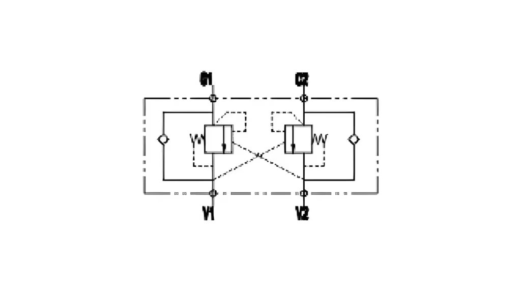
On a hydraulic schematic, an overcenter valve is drawn as a square body containing two elements: a spring symbol (showing the adjustable pressure setting) and a diagonal line representing the variable restriction that opens under pilot pressure. This is the detail that distinguishes it at a glance from a plain check valve symbol, which uses a triangle instead of the diagonal line. A double overcenter valve simply mirrors this symbol twice within one body outline, one set for each flow direction, with a shared or cross-connected pilot line depending on the specific circuit.
Overcenter Valve vs. Counterbalance Valve — the Short Version
In casual industry use, “overcenter valve” and “counterbalance valve” are often treated as the same thing, and the two terms do describe closely related hardware. Where manufacturers draw a line, it’s usually about emphasis: overcenter valves are generally associated with dynamic, direction-changing loads and higher pilot ratios (3:1 to 5:1), while counterbalance valves are more often associated with steady, gravity-driven static holding and lower pilot ratios (2.5:1 to 3:1). For a full side-by-side comparison — including symbol differences, application examples, and common misconceptions — see our complete guide to overcenter valves vs. counterbalance valves.
Where Overcenter Valves Are Used
Overcenter valves show up wherever a hydraulic actuator has to hold a load against gravity or momentum without operator input at that instant. Common applications include:
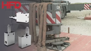
- Truck-mounted crane outriggers — holding single-acting outrigger legs in position under a rotating, shifting load
- Boom and knuckle-boom cranes — controlling lowering speed on the main lift cylinder regardless of load weight
- Winches and hoists — maintaining controlled cable tension during lowering, often with a double valve on the motor
- Aerial work platforms and scissor lifts — preventing platform drop if a hydraulic line is compromised
- Mobile equipment on grades — preventing runaway movement during downhill or sloped operation
Several of these — outrigger circuits especially — are covered in more depth in HFD’s application-specific guides linked throughout this article.
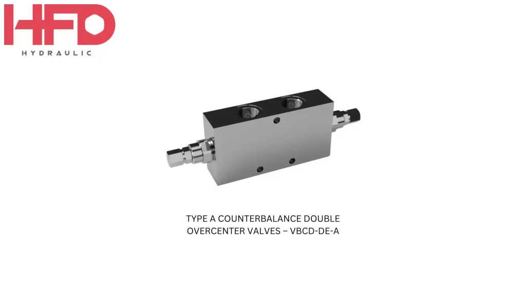
Featured Product: HFD VBCD-DE-A Double Overcenter Valve
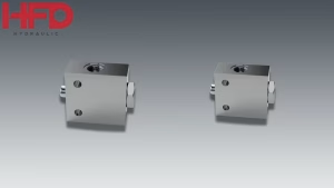
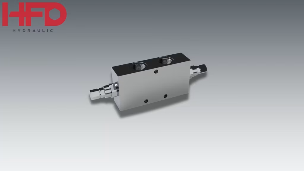
For circuits where the load can drive motion in either direction, HFD Hydraulic’s Type A Double Overcenter Valve (VBCD-DE-A) is built for in-line mounting directly at the actuator. Typical specifications for this valve series:
| Spec | Value |
| Body construction | Zinc-plated steel body, hardened and ground internal parts |
| Seals | BUNA-N (NBR) standard |
| Pilot ratio | 4.5:1 |
| Maximum pressure | Up to 350 bar |
| Flow rating | Up to 40–60 L/min, depending on port size |
| Port sizes | G1/4, G3/8, G1/2 |
| Standard pressure setting | 320 bar (valve setting should be at least 1.3× the maximum load-induced pressure) |
Its dual check-and-relief construction blocks reverse flow in both directions, making it a fit for double-acting cylinders and motors where the load doesn’t have a single, consistent direction of travel — unlike the single VBCD-SE-A used in the outrigger circuit, which only needs to hold one direction.
How to Choose an Overcenter Valve
At a minimum, matching an overcenter valve to an application comes down to:
- Load direction — single (one direction) or double (both directions)
- Pilot ratio — lower for stable static holding, higher for dynamic, direction-changing loads
- Maximum working pressure and flow — must exceed the highest load-induced pressure and match actuator flow at operating speed
- Port size and mounting style — in-line, cartridge, or manifold-mounted, matched to the actuator’s ports
For the full walkthrough of these selection criteria — including sizing math and common mistakes — see our complete guide to selecting a counterbalance valve.
An overcenter valve is a small component with an outsized job: keeping an actuator exactly where it’s supposed to be, whether the system is idle or the load is actively trying to move on its own. Understanding the check/relief mechanism, pilot ratio, and single-vs-double distinction is the foundation for specifying the right valve for any load-holding circuit.
HFD Hydraulic manufactures a full range of single and double overcenter/counterbalance valves for mobile and industrial hydraulic applications. Contact our team to discuss valve sizing for your application.