Quick Overview: Stroke End Valve vs Limit Switch and Solenoid Valve
- A stroke end valve stops cylinder flow through direct mechanical contact. The electronic alternative uses a limit switch to signal a solenoid valve.
- The mechanical valve needs no electrical power for the stop function. The electronic route depends on current at the solenoid coil.
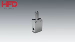
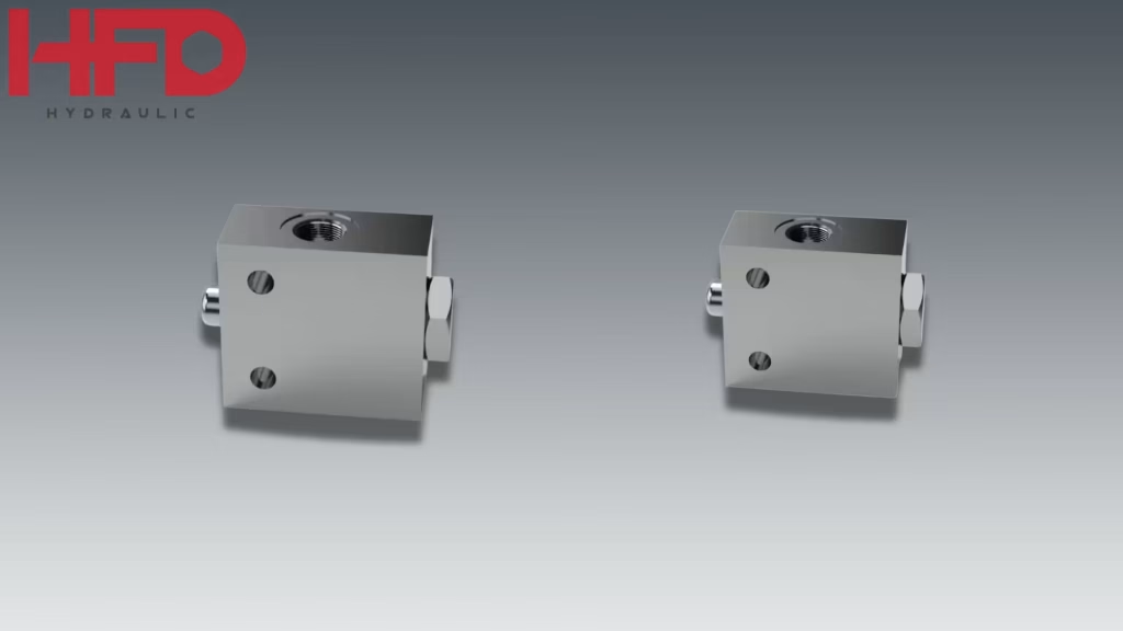
- HFD’s FCA (normally open) and FCC (normally closed, double locked) stroke end valves handle up to 300 bar and 60 l/min.
- Circuits above 60 l/min, or stops that must adjust mid-stroke, call for a different approach.
Every hydraulic cylinder eventually runs out of stroke. What happens next depends on how the circuit knows to stop. When a cylinder reaches its hard stop while the pump is still delivering flow, system pressure rises sharply until the relief valve opens. Repeated over hundreds of c ycles per shift, that loads seals, mounting pins, and brackets.
A stroke end valve (also called an end of stroke valve) prevents this by cutting flow through direct mechanical contact. The alternative is electronic: a limit switch signals a solenoid valve. Both approaches work, and they suit different machines.
This article compares the two on how they stop the cylinder, where each can fail, and where each runs out of range. It uses HFD’s FCA and FCC stroke end valves as the mechanical reference. For a general introduction to the valve, start with our end of stroke valves guide.
How a Stroke End Valve Stops the Cylinder
A push-button stroke end valve works through direct physical contact. A bracket or actuating plate on the moving component reaches the valve button and depresses it through its stroke, which closes the internal flow path and stops oil supply to the cylinder. When the cylinder retracts, contact breaks, the spring-loaded button releases, and the valve reopens.
These valves come in two basic states. HFD’s guide lists the FCA as normally open and the FCC as normally closed. Cable-actuated versions also exist for tipping bodies, and our dump truck article covers that configuration.
The stop function itself needs no electronic components and no operator input. The valve responds to where the cylinder is, not to a pressure reading or an electrical signal.
How the Electronic Alternative Works
A solenoid valve controls fluid flow by changing the valve’s position when electric current passes through a solenoid coil (Angadi et al., Engineering Failure Analysis, 2009). In an electronic end-of-stroke arrangement, a limit switch or sensor detects the rod position, and its signal drives the solenoid valve. Research on hydraulic position control describes this kind of setup: a double-acting cylinder, solenoid directional control valves, and electro-mechanical limit switches that sense the position of the cylinder rod (Journal of Engineering and Sustainable Development).
The stop point in this arrangement depends on a sensing element, a solenoid valve, and the electrical connections between them. For HFD’s directional solenoid valves, see our articles on pilot-operated directional solenoid valves and the complete guide to directional solenoid valves.
Stroke End Valve vs Limit Switch and Solenoid Valve: Side by Side
| Factor | Stroke end valve | Limit switch + solenoid valve |
| Stop trigger | Physical contact with the valve button | Electrical signal from a limit switch to the solenoid coil (Angadi et al.; JEASD) |
| Electrical power for the stop | None required | Required at the solenoid coil (Angadi et al.) |
| Parts in the stop chain | Valve and actuating bracket | Limit switch, solenoid valve, and their electrical connections (JEASD) |
| Flow range | Up to 60 l/min for the FCA and FCC | Set by the solenoid valve selected |
| Unactuated state | FCA normally open, FCC normally closed | Both normally open and normally closed solenoid valves are used (Angadi et al.) |
The practical difference is where the decision to stop is made. In the mechanical version it is made at the valve by a bracket’s position. In the electronic version it is made by a signal that has to travel from the switch to the coil. Neither is better in every case. Each fits a different set of conditions, covered below.
Where the Valve Sits in the Circuit
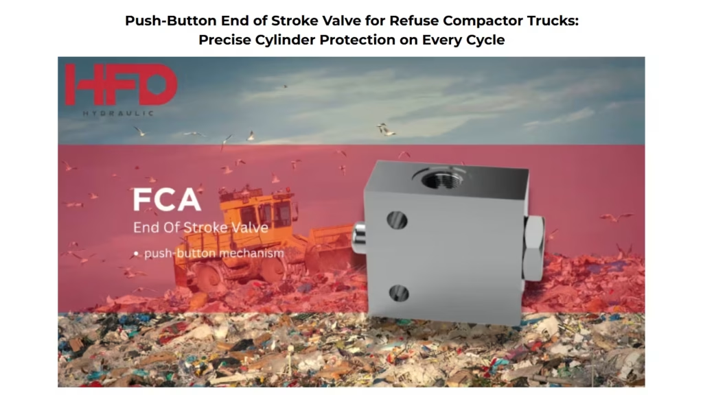
In a push-button stroke end valve installation, the valve goes in the pressure line feeding the cylinder port that receives flow during the stroke you want to limit. In HFD’s compactor example, that is the cap-end port of the compaction cylinder: flow enters the valve at port P, leaves at port A, and continues to the cylinder. The valve controls only that extension path, and the directional control valve still governs the retraction circuit. Where two cylinders work in parallel, each needs its own valve on its cap-end line for consistent protection (HFD refuse compactor article below).
Where Each Approach Can Fail
Stroke end valve
HFD’s troubleshooting table for the FCA points to mechanical causes. If the bracket is misaligned or has shifted, the button is not fully depressed and the cylinder does not stop. If the bracket makes contact too early, the cylinder stops short of full stroke. A button that does not return after retraction points to contamination in the valve body or spring fatigue. The same article notes that angled contact accelerates button wear and can cause the valve to close incompletely.
These faults can be found by inspection: check the button face, the contact pad, and the bracket fasteners at regular service intervals.
Limit switch and solenoid valve
On the solenoid side, one study of a solenoid valve under accelerated testing found that failure was caused by overheating and breakdown of the coil insulation. Once the coil shorted, its resistance dropped and the current rose. The same paper’s literature review reports that too little or too much voltage can overheat a solenoid valve, that high cycling rates and duty cycles generate heat, and that a blocked or stuck armature can overheat because power stays applied while it tries to free itself. It also lists a valve that fails to close when de-energized because foreign matter lodges on the seat.
Two caveats apply. The study tested an automotive transmission valve at 100°C ambient and above its rated voltage to produce failures quickly, and the authors note that many solenoid valves run for years without failure when operated at rated conditions. We also did not find an authoritative source comparing failure rates between the two approaches, so this article does not claim one is more reliable than the other.
Where a Stroke End Valve Reaches Its Limits
Flow ceiling. Both HFD stroke end valve families top out at 60 l/min: the FC03A in the FCA family, and the FC03C and FCS03C in the FCC family. A circuit with higher flow needs a different valve for the stop.
Fixed trigger point. The push-button design suits a consistent linear path and a fixed contact point. HFD describes it as a fit where repeatability at the stop point matters more than adjustable mid-stroke control.
Travel and alignment. The FCA’s maximum button stroke is 7 mm. The bracket must be sized so the full 7 mm is reached before the cylinder hits its mechanical hard stop, not at the same moment
Pressure after closing. The valve closes while the pump keeps running briefly, so line pressure rises and the system relief valve or an unloading circuit handles the excess flow.
Fluid compatibility. The FCA’s NBR seals are rated for mineral-based hydraulic oil. With biodegradable or fire-resistant fluid, confirm seal compatibility with the fluid supplier first.
Installation Points That Affect Reliability
HFD’s installation guidance for the FCA centers on the bracket and the mounting. The bracket should be rigidly attached to the moving component, with no flex or play, and should meet the center of the button face. A flat contact pad is preferred over a sharp edge, because distributed contact load reduces wear on the button face. The valve itself should be mounted to a fixed structural member, away from thin panels or unsupported sections that flex or vibrate heavily, and in a spot that can be reached for inspection.
How to Choose Between the Two
| Your situation | Better fit | Basis |
| Consistent linear stroke, fixed stop position, flow up to 60 l/min | Stroke end valve | Matches the conditions HFD lists for push-button valves and the FCA and FCC flow limits |
| You want no electrical components in the stop function | Stroke end valve | The push-button valve needs no electronic components |
| The stop position must adjust mid-stroke | Evaluate the limit switch and solenoid route | HFD notes push-button valves suit repeatability more than adjustable mid-stroke control |
| Flow above 60 l/min | Look beyond the FCA and FCC | Their maximum flow is 60 l/min |
One more distinction is worth keeping in mind. A stroke end valve responds to position. A valve that responds to pressure, such as the one discussed in our sequence valve in outrigger circuits article, works on a different principle. Choose by what the circuit needs to react to, not by which part is more familiar.
HFD FCA and FCC Stroke End Valves
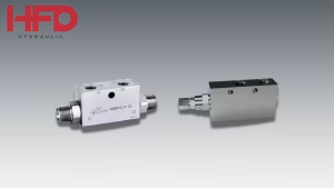
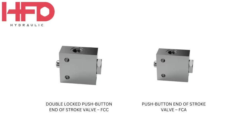
HFD supplies two push-button stroke end valve families, both listed under stroke end valves.
| Specification | FCA | FCC |
| Unactuated state | Normally open | Normally closed, double locked |
| Variants and max flow | FC02A: 30 l/min; FC03A: 60 l/min | FC02C and FCS02C: 30 l/min; FC03C and FCS03C: 60 l/min |
| Port size | G3/8 or G1/2 | G3/8 or G1/2 |
| Max pressure | 300 bar | 300 bar |
| Fluid | Mineral-based oil, 10 to 200 cSt | Mineral-based oil, 10 to 200 cSt |
| Weight | 0.75 to 0.77 kg | 0.79 to 1.30 kg |
Sources: HFD FCA and FCC product pages; normally open and normally closed states from the HFD guide.
The FCA has a steel body, NBR seals, a 7 mm maximum stroke, and a maximum contamination level of 18/16/13 under ISO 4406. Its two sizes share the same body dimensions, pressure rating, stroke, and actuation mechanism, and differ only in flow capacity and port size. The FC03A is the larger of the two, and HFD’s compactor article treats it as the safer pick when in doubt, since extra flow capacity has no mechanical downside in that circuit position.
The FCC is the double-locked option. The product page does not describe the locking mechanism in detail, so ask HFD for the datasheet if the locking behavior matters to your circuit.
Choosing Your Next Step
If your circuit has a fixed stop position and flow within 60 l/min, a stroke end valve keeps the stop function mechanical. If it needs an adjustable stop, the limit switch and solenoid valve route is the one to evaluate. Browse HFD’s stroke end valves, or contact HFD with your cylinder bore, flow rate, and fluid type so the team can confirm the right model.